The Polarization Microscopy Principle

An introduction to microscope imaging with polarization contrast

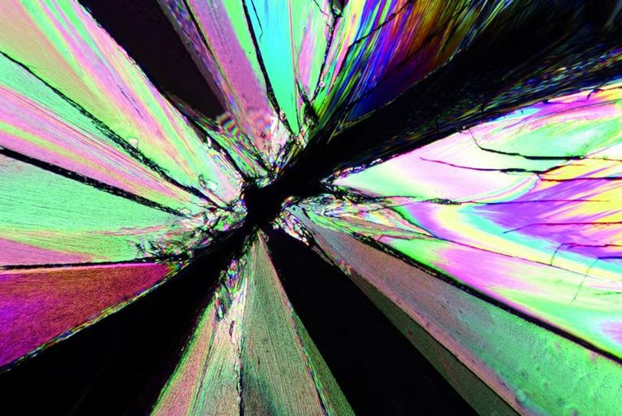
Image of a tartaric-acid crystal taken with polarization microscopy. Tartaric acid, a diprotic, aldaric carboxylic acid, is a naturally occurring organic compound notably found in grapes. Tartaric_acids_polarization.jpg

Polarization microscopy is routinely used in the material and earth sciences to identify materials and minerals on the basis of their characteristic refractive properties and colors. In biology, polarization microscopes are commonly used for identification of birefringent structures, like crystals, or for imaging of cellulose in the walls of plant cells and starch grains. This article gives an overview of the basic principles of polarization microscopy.

Birefringence Is the Key to Polarization Microscopy

Birefringent materials are optically anisotropic and the refractive index of such materials depends on the direction in which light propagates through it. Birefringence means a ray of unpolarized light is divided into two rays by refraction when passing through the material. Birefringent materials have a highly ordered molecular structure, like crystals of calcite or boron nitride. Biological specimens  also can be birefringent, for example cellulose and starch. In combination with linearly polarized light, birefringence can be used in microscopy to achieve interference of the two resulting rays, which can produce color effects like rings and the highlighting of structures.

Related articles

Macroscale to Nanoscale Pore Analysis of Shale and Carbonate Rocks

Physical porosity in rocks, like shale and carbonate, has a large effect on the their storage capacity. The pore geometries also affect their permeability. Imaging the visible pore space provides…
Mouse lung sections

Studying Pulmonary Fibrosis

The results shown in this article demonstrate that fibrotic and non-fibrotic regions of collagen present in mouse lung tissue can be distinguished better with polarized light compared to brightfield.…
Images of the same area of a processed wafer taken with standard (left) and oblique (right) brightfield illumination using a Leica compound microscope. The defect on the wafer surface is clearly more visible with oblique illumination.

Rapid Semiconductor Inspection with Microscope Contrast Methods

Semiconductor inspection during the production of patterned wafers and ICs (integrated circuits) is important for identifying and minimizing defects. To increase the efficiency of quality control in…

Alignment and Beam Path of a Polarizing Microscope

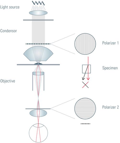
A conventional optical microscope needs at least two additional components to perform polarized light microscopy. For detection of birefringence, linearly polarized light must be used for illumination of the specimen or sample. Therefore, two polarizing filters have to be inserted into the beam path of the microscope. The first polarizing filter produces polarized light which illuminates the specimen and the second polarizing filter, called the analyzer, restricts the passage of light which is detected to refracted light with a specific polarization.

The transmission axes of the polarizing filters have to be crossed at an angle of 90°, meaning the extinction axis of one filter is aligned with the transmission of the other, to achieve the so called “dark position”. When the polarizing filters are set at this position, no light will pass to the camera or eyepieces and the image will be dark. Setting up the dark position is an important step for polarized light microscopy as it ensures that only light which experiences a change in polarization  after passing through the specimen will be visible.

Polarizer and Analyzer

When light passes through the first polarizing filter, it is linearly polarized. If some of the linearly polarized light passes through the correct polarization plane of a birefringent material, it is refracted, split into two rays, and the polarization plane of these rays is turned by 90°. The refracted rays then pass through the second polarizer (analyzer), if it is aligned correctly (i.e., 90° relative to the first polarizing filter). Therefore, for this setup only birefringent specimens or materials produce an image when observed with a polarized light microscope.

It is important that the polarization axis of the birefringent material being observed is the same as that of the polarized light produced by the first polarizer filter. For this reason, many polarization microscopes are equipped with a rotating stage to ensure easy alignment of the sample’s polarization plane with the one of the first polarizer. Various accessories are available for special applications where polarization microscopy is useful.

A Bertrand lens is used in the microscope for conoscopic observation of interference patterns from crystals where the light rays are focused in the plane of the objective rear aperture [1,2]. Additionally, a retardation plate or compensator is useful for quantitative analysis of birefringent specimens.


Applications for Polarizing Microscopes

Fig. 3: Polarization microscope image of a fly which is embedded in Baltic amber. Although amber is an amorphous substance and, in theory, optically isotropic, the flow structures of the resin due to internal strain, as well as the strain caused by any inclusions like this fly, can be visualized with polarized light. The use of polarized light and the first-order red compensator lead to images with intensive colors of a normally golden amber. Image taken with a combination of darkfield and incident light (using a glass fiber), crossed polarizers, red-1 compensator, and HDRI tone mapping. Courtesy of Michael Hügi, Swiss Gemmological Society, Bern, Switzerland.

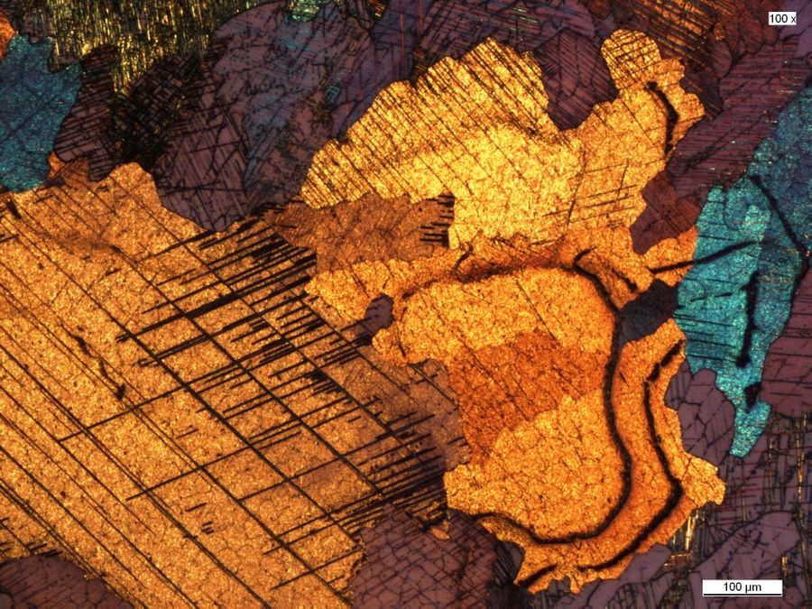
Fig. 4: Image of a cold-rolled, Beraha etched cobalt alloy taken with polarization microscopy. Examination of the microstructure and morphology are crucial for materials science, failure analysis, and quality control. Color contrast and specific microstructure formations can frequently be enhanced by observation of the etched samples with a polarization microscope. Courtesy of Ursula Christian, University of Pforzheim, Germany.

Fig. 5: Crystal of tartaric acid imaged with polarization microscopy. Tartaric acid is a naturally occurring diprotic, aldaric carboxylic acid which is most notably found in grapes.

Fig. 6: Image of an aluminum (Al) alloy etched with Barker’s reagent taken with polarization microscopy. The etching enables the grains of the Al alloy to be revealed with polarized light.

Related articles

Neurons imaged with DIC contrast.

Differential Interference Contrast (DIC) Microscopy

This article demonstrates how differential interference contrast (DIC) can be actually better than brightfield illumination when using microscopy to image unstained biological specimens.

Metallography – an Introduction

This article gives an overview of metallography and metallic alloy characterization. Different microscopy techniques are used to study the alloy microstructure, i.e., microscale structure of grains,…
Basalt imaged with crossed polarizers

Digital Microscopy in Earth Science

Classical polarized light (compound) microscopes can only be used for prepared samples, because the working distance they offer is insufficient for whole samples. This means that thicker and bigger…
Scroll to top