Introduction
Electron microscopes such as transmission- and scanning electron microscopes (TEM and SEM, respectively) are widely used to obtain high-resolution structural insight into biological samples or inanimate materials.
Ultramicrotomy is the most common method to obtain ultrathin sections of < 100 nm for examination in the TEM/SEM. In room temperature sample preparation, small pieces of samples are embedded in epoxy or acrylic resin, excessive resin is then removed by trimming and the specimen is sectioned into ultra thin sections (50 nm - 100 nm) using either a glass or diamond knife.
The trimming process is an important step to remove excessive sample-free resin, to reveal the specimen and to generate a block-face containing the regions or cells of interest for subsequent sectioning.
In the current standard workflows the actual target region cannot always be identified directly on the ultramicrotome by using the fitted standard stereo microscope. Instead, exemplary sections are stained and transferred to external widefield microscopes with higher magnification to examine if the target plane of the specimen is already reached. Afterwards tedious adjustments on the ultramicrotome must be performed to ensure sectioning without sample loss.
To avoid these risky and laborious transfers and readjustments it would be beneficial to directly recognize target regions on the ultramicrotome. One method to label target regions is fluorescence labeling. This is also possible for EM samples by preserving in-resin fluorescence using acrylic polymers.
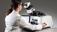
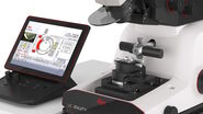
To fill this gap, an ultramicrotome providing fluorescence observation with cellular resolution during trimming and sectioning would be needed. Leica´s automated ultramicrotome UC Enuity equipped with the M205 FA for fluorescent imaging exactly provides this solution.
Here we show how UC Enuity can be used to identify fluorescent cells of interest, how a block-face containing the cells of interest can be trimmed automatically and how the cells of interest can be visualized in the sections without transferring to external microscopes.
In-Resin Fluorescence
Room temperature sample preparation starts with embedding the sample into resin. One method to label target regions is fluorescent labeling.
There are several protocols available describing how e.g. fluorescent cells can be prepared, including cell culture, fixation, high pressure freezing, dehydration and embedding in acrylic resin.
Typically acrylic resins like LR White (room temperature infiltration and polymerisation by heating) or LowicrylTM HM20 (for freeze substitution and polymerisation in UV light) are used depending on the protocol.
The advantage of using acrylic resins is to permit an adequate retention of the ultrastructure together with a good antigenicity and/or fluorescence capability.
To obtain a good ultrastructure in the TEM together with maintaining the fluorescence, protocols with high pressure freezing and freeze substitution were developed:
E.g.
A Single Method for Cryofixation and Correlative Light, Electron Microscopy and Tomography of Zebrafish Embryos.
Nixon, S. J. et al. 2009
Traffic 10 (2), 131–136. doi:10.1111/j.1600-0854.2008.00859.x
or
Correlated Fluorescence and 3D Electron Microscopy with High Sensitivity and Spatial Precision.
Kukulski, W. et al. 2011
J. Cell Biol. 192 (1), 111–119. doi:10.1083/jcb.201009037
In addition, there is a review on the topic with all relevant other authors:
One for All, All for One: A Close Look at In-Resin Fluorescence Protocols for CLEM.
Heiligenstein X. et al.
Front Cell Dev Biol. 2022 Jun 30;10:866472. doi: 10.3389/fcell.2022.866472. PMID: 35846358; PMCID: PMC9280628.
Optical Needs
To support the identification, trimming and sectioning on the ultramicrotome specific optical needs apply for the stereo microscope used. In the following some optical aspects are discussed.
Magnification and resolution
Ultramicrotomes are equipped with stereo microscopes to magnify the area of interest while maintaining the 3D impression as basis for the necessary precise handling of sample and knife in relation to each other during trimming and sectioning. Typical magnifications are in the range from 6.7x up to 77x depending on the objective and eyepieces.
As many mammalian cells in culture have a diameter of about 10 µm on a substrate, the resolution of the optical system should be at least 5 µm to resolve individual cells (following the socalled Nyquist frequency). This is particularly important if the cells are attached to each other and not well separated.
Leica’s UC Enuity can be equipped with either the stereo microscope M80 for non-fluorescent applications or M205 FA for fluorescence applications. The “80” or “205” represents the zoom range of 8 or 20.5, respectively.
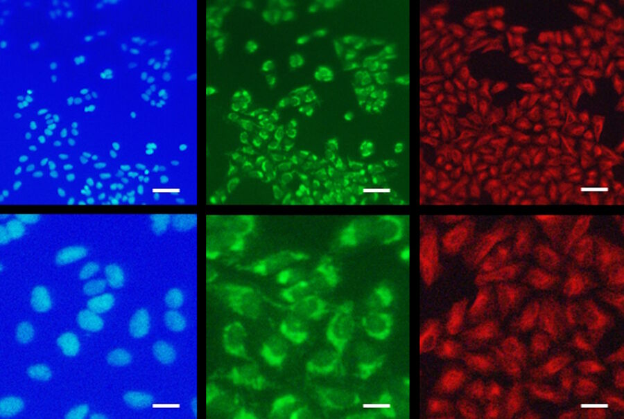
Thus, the stereo microscope M205 FA for fluorescence application provides stepless magnifications ranging from 7.8x to 160x using the standard 0.63x lens with a working distance of 9.7 cm. At the same time the resolution ranging from 25 µm to 3 µm is capable to resolve individual cells in both brightfield and fluorescence while even subcellular pattern can be discriminated, i.e. mitochondrial staining pattern (Figure 1).
Fluorescence capability of the stereo microscope
To perform fluorescence on a stereo microscope many challenges appear, which have been solved by Leica Microsystems. To get rid of the excitation light, which is orders of magnitudes brighter than the emission, Leica uses the patented TripleBeam technology where the excitation light is reflected away from the emission light path. This allows fluorescence observation of the specimen without reflexes and with good contrast, which is crucial for precise trimming (TripleBeam technology).
Intensity of the fluorescence
Depending on the number of fluorophores attached to the target molecule the intensity of the signal varies strongly. If it is not possible to visualize the sample in a standard widefield microscope it is neither in a stereo microscope with rather limited opening angle of the objective. This is particularly true, as on an ultramicrotome a working distance of several centimeters is necessary to not touch or damage knife or sample. This needs a good balance between magnification, opening angle (numerical aperture), working distance and light collection efficiency. On the UC Enuity equipped with the M205 FA this resulted in the 0.63x objective with a working distance of almost 10 cm.
In case the signal is hard to see by eye, it might be possible to visualize faint signals by increasing the exposure time of the digital camera into the range of ½ second or higher. Still, it is strongly dependent on the sample, if the fluorescence intensity is high enough to visualize and use it for (automatic) trimming on an ultramicrotome.
Automatic Trimming using Fluorescence
In the following, we show an exemplary workflow using the automatic ultramicrotome UC Enuity equipped with the M205 FA including the visualization and selection fo fluorescent target cells as well as cutting sections that contain the fluorescent target cells. The aim was to visualize complete cells i.e. the direct membrane staining and to keep the procedure simple. For maintaining specific intracellular fluorescence structures the protocols mentioned above including high pressure freezing and freeze substitution should be used.
Placing fluorescent cells on sapphires
Mammalian cells were grown over night on sapphires. Sapphires were coated with a carbon finder grid to adjust the orientation in the flow through chambers of the automatic freeze substitution system (Leica EM AFS2). Cells were stained with CellTrackerTM Green (Thermofisher) and chemically fixed with 2 % glutaraldehyde. Sapphires were transferred into the EM AFS2 and automatically dehydrated with increasing ethanol concentrations. Infiltration and polymerization was done using LowicrylTM HM20. Afterwards the sapphires were removed from the resin to present the cells for sectioning.
Getting an overview of the specimen
After mounting the sample into the UC Enuity an overview of the sample surface was created in brightfield and fluorescence mode (GFP filter: excitation 450 - 490 nm and emission 500 - 550 nm; Figure 2).
Improved sample visualization with the help of the Mesacut mirror
In order to obtain a light gap between the knife and the sample for alignment and to get a reflection of the water surface on the knife boat for the sectioning process, the M205 FA stereo microscope is mounted in a 20° angle. Hence, a frontal view onto the sample surface is not possible.
To get a frontal view, a flexible mirror the so-called Mesacut mirror (mesa = table mountain) can be used (Figure 3). The angle of the mirror is flexible and can be adjusted by the users according to their needs.
Defining the block-face parameters for automatic trimming
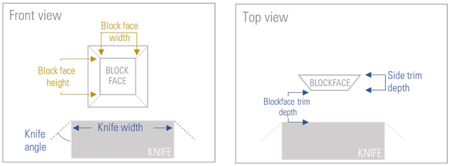
To automatically trim the sample towards the desired block-face six different parameters have to be defined (Figure 4). The software workflow of the UC Enuity guides the user to set the parameters.
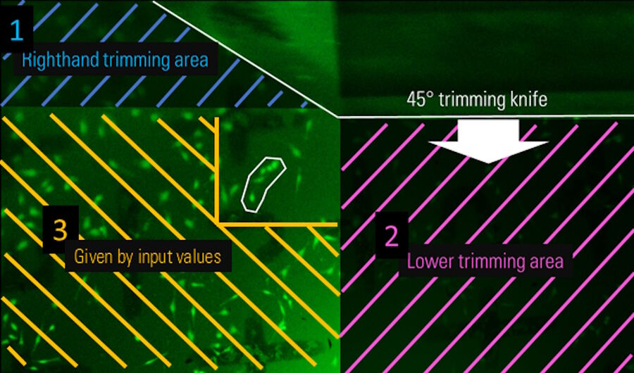
First, the width of the knife needs to be entered to ensure that the knife covers the final block-face size. Secondly, the trimming knife inclined angle must be set. In this step, the UC Enuity automatically calculates the knife positions in x-direction when using a knife with 45° inclined angle. Thirdly, the desired block-face width and height is needed. Next, the trim depth must be set to define how much of the sample initially should be trimmed away until the final front face is reached. Finally, the side trim depth of the final block must be set. Figure 5 shows one exemplary screenshot of the software guiding the user through the Auto-Trim workflow for defining the input values.
Defining the edges of the block-face for automatic trimming
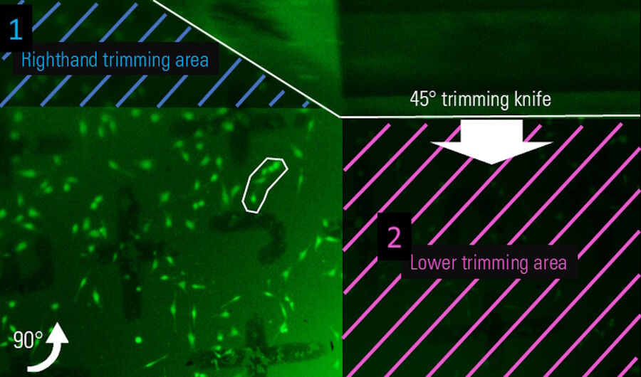
After setting the numerical values, the absolute position of the block-face on the sample must be defined. This is done by setting the left edge of the knife to the right edge of the desired block-face which contains the target structure, a group of cells marked with a white region of interest (Figure 6; Note: The knife is visible on the top of the image as this is the Mesacut mirror view). Afterwards the sample is rotated 90° clockwise and the lower edge of the block-face is set (Figure 7). Finally the resulting block-face size is calculated by the numerical input values from the software workflow (Figure 8).
Due to the technique using cells on sapphires, the cells were located directly beneath the surface of the block-face, hence, no removal of material on the front face was necessary.
Sidenote: For the approach of target planes deeper within the resin, 3D data of the sample created by a confocal microscope or a micro computer-tomograph (µ-CT) can be used. The UC Enuity provides a software-workflow to directly load 3D renderings of samples for target plane trimming. Note: A target plane can be trimmed with this technique and no block-face.
Automatic trimming process
During the automatic trimming process the final block-face is created without user interaction. The automated process includes the positioning of the knife and sample according to the defined positions, the cutting of the defined trimming depths and the sample rotation. This allows the users to gain some precious time for other activities.
Result of the automatic trimming process
Figure 9 shows the final result of the automatic trimming process. The group of fluorescent target cells is located in the center of the block-face (white arrow) and the edges are removed according to the input values.
Is the target in the section?
After the automatic block-face trimming we sectioned the block-face to prove that the fluorescent target cells can be visualized in the sections on the UC Enuity equipped with the M205 FA. After one partial section, the cells were visible already in one of the first full sections (Figure 10).
Summary
In this article we learned, that in-resin fluorescence can be used to target cells in a block-face and finally on sections. Furthermore we showed, that the M205 FA fitted to the UC Enuity is perfectly capable to resolve individual cells and even subcellular pattern. This avoids tedious transfers to other microscopes during the approach of the target plane resulting in less risk of sample loss and time for trimming and sectioning. The UC Enuity software workflow helps to guide through the set up process and the fully automated trimming process gives back even more precious time to the user.
Of course, the Auto-trim function of the UC Enuity can be used with standard brightfield illumination allowing to gain the benefits described above without in-resin fluorescence as well (as long as the target is visible without it).
In line with the increasing popularity of electron microscopy in general and volumetric electron microscopy in particular, the efficient trimming becomes more and more important to quickly find target structures as soon as the specimen is in the EM. The UC Enuity with its automatic trimming function helps to trim the sample efficiently in order to finally reduce the beam time resulting in lower costs and less time-to-result.
Acknowledgements
The author likes to thank particularly Felix Gaedke, PhD (CECAD Cologne, Germany) for providing the samples and knowledge in many ways; and Astrid Schauss, PhD, head of CECAD/CMMC imaging facility, Cologne, for supporting the authors way into the deep of EM workflows.


